Students investigated how far three steel springs of different stiffness stretch when a force pulls on them. They hung known weights on each spring so that the weights pulled straight down with forces of 1, 2, 3, 4, and 5 newtons (N), and they measured how much each spring stretched.
Three vertical steel springs, labeled Spring A, Spring B, and Spring C, were each hung from a fixed clamp. The springs were made from wire of different thickness, so they differed in stiffness. For each trial, a hanging weight was attached to the lower end of one spring so that it pulled on the spring with a known force. The forces used were 1 N, 2 N, 3 N, 4 N, and 5 N.
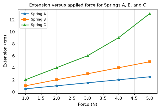
The extension of a spring is the increase in its length compared with its unloaded length. After each weight was added and the spring stopped moving, the extension was measured in centimeters (cm) with a ruler. The same set of forces was applied to each spring in turn, and the results are shown in Table 1. Figure 1 plots extension against force for all three springs.
A spring obeys a simple proportional rule only up to a point called its elastic limit: below that load, extension is directly proportional to force, so a graph of extension against force is a straight line passing through the origin. If a spring is stretched past its elastic limit, the line bends and the proportional rule no longer holds.
Table 1: Extension of each spring (cm) for forces from 1 N to 5 N
| Force (N) | Spring A extension (cm) | Spring B extension (cm) | Spring C extension (cm) |
|---|
| 1 | 0.5 | 1.0 | 2.0 |
| 2 | 1.0 | 2.0 | 4.0 |
| 3 | 1.5 | 3.0 | 6.0 |
| 4 | 2.0 | 4.0 | 9.0 |
| 5 | 2.5 | 5.0 | 13.0 |
Figure 1: Extension versus applied force for Springs A, B, and C